Image above captured on the upper deck of the layout where scenery has progressed to some extent...
Shot with Olympus C-750

Welcome to the SP Oregon Division!

An N Scale RR depicting the good old days along "The Friendly".

Thursday, August 13, 2020

Lumber Mill Structures


I have reworked some of the trackage for my Pope and Talbot lumber mill at Oakridge. There are now two tracks in the back to handle the increase of woodchip traffic that JMRI Ops (generated switchlists) needed to keep car flow moving. The track arrangement is actually closer to the original SPINS configuration this way (my only current view of what trackage looked like) Was happy to find Republic Locomotive Works still offered their (laser) woodchip loader that I needed to have a matching pair. 
Still begging for some stain

 I also picked up one of their bin loaders for my planned fleet of chip truck haulers (Hello, Trainworx?). This was another laser wood kit that I still have to add the ladders onto, but its got a coat of green paint (since this shot) and getting close to completion. 

I also relocated a couple other tracks which made more room for placement of my loading warehouse kitbash. It was a combination of two Bingen kits from Reiten Models (well executed laser wood kit). 

The mill property fills a corner that was landscaped with hardshell scenery. It has recently had the stark white plaster covered with some ground color (ha, it could be 20 years old at this point). I relocated the Walthers lumber mill (another unfinished kitbash) from where the warehouse sits more to the front since its footprint wasnt playing nice for operator access (I wish it had been more feasible to invert it the opposite configuration). Eventually there will be an array of pneumatic tubes blowing sawdust to all the loaders and the slash burner. Pondering where to cut in a service road as the whole plant is currently land locked...

Wednesday, August 12, 2020

Hampton Bridge


SP’s Willamette river crossing at the tail of Lookout Point Reservoir was via three through truss sections (basically) in the middle of three plate girder sections. 
Ron Harr image:

Space on the layout here only permitted half that, with one thru truss and a plate girder on each side of that. It was hard for me to follow through on construction due to the model being so condensed, but I continued to persevere through with an attempt to Espee-ize the more prominent components.
For construction, minor modifications to the Atlas (early style) plate girder bridges entailed raising the roadbed, and adding gussets on the inside of the plate girders. I modified the Atlas (late version) thru truss bridge from an open deck to a ballasted deck, and added handrailing on both sides.

 I also reworked the shape of the portal openings, which regained lost clearance from the ballasted deck conversion. Other mods included adding plates where the bridge sections are connected together, and Micro Engineering cast metal bridge feet.  
This bridge is part of the overall scene that includes the west end of Hampton siding, an important addition to operations of the layout. The opening behind the bridge is to help crews view train clearances and signal indications from opposing sides. Eventually a tree line will mostly obscure the opening in an effort to keep the scene fluid. 

I still need to modify the styrene bridge piers that Art built to accept the offset foot patterns, and paint the overall structure, then ballast will go in after the ground cover. 

Tuesday, August 11, 2020

Eugene Yard Structures


 With scenery having progressed through the yard area now, I have begun working on some related structures. The bigger projects to come will be the engine house and sand towers around the diesel service area. Meanwhile I have a few of the DeLuxe office / maintenance sheds, and a BLMA yard office filling some open space, but needed more structures to bring things alive. So I pulled out a couple brass Alkem yard light tower kits that had been sitting in a box for years. They arent perfect for what Espee had in this yard, but I was ok with them for now until something better comes along (or I want to take the time to scratchbuild new top sections). It was a bit of a challenge for me in getting the tower sections bent. I cobbled together some straight edges and clamps to hold things square while I proceeded through the bends, but felt uneasy about making the wrong move due to lack of proper tools. 

Luckily things went well, and the rest of the project fell together pretty smoothly. I soldered the larger sections that were readily accessible and used ACC for assembly of the finer details. I built two of these kits together in an effort to be more productive with the assembly process. The lamp holders still need to be bent into shape, and then they will receive some black paint. They each have a home on opposing ends of the yard. 

While I had sharpened my skills with these kits, it was a good time to drag out a pair of old brass yard tower kits I had from Traincat. These were a close match to what was on Espee’s property back in the day.
With these kits being a bit more complicated, I decided to get a 3-1/2” metal seamer tool from Harbor Freight, to ensure each bend was sharp and square. See link Hand Seamer. I would have preferred a few more line up keys on some steps of the overall kit, but they were fun projects to build otherwise. 

I have all the glass cut out and ready for Alclad tinting, and I recently picked up the Vallejo paint colors for both these projects. 
East end Eugene Yard

You can barely see the other family members at the opposite end of the yard.


Monday, August 10, 2020

Scenery Progress

The layout has been neglected scenery wise for far too long. I just seemed to get stuck in a rut daunted by all the rough scenery everywhere, and couldnt seem to make any progress. Art offered to help out, and over a number of visits we got a large swath of foam base contouring done with his hot knives (before the covid hit). Thanks Art!  I have been progressing with renewed enthusiasm ever since.  One of the main reasons I switched from hardshell plaster to the extruded foam was to make it easier for planting trees. Even using silicone caulk in between blocks was of concern in this regard, so I used Loctite expanding foam in a can where possible. Most minor carving was done with a knife, and final contouring was done with rough and med grades of sandpaper. Minimal filling was also done with Sculptamold and Dap lightweight spackle. 

Basic scenery has finally made completion around both decks of the layout including a coat of earth color tone.  No more white plaster or pink foam showing anywhere... but still lots of scenery work to do. I find myself falling back in my old ways from the construction industry, where everything needs to be done in a production line mentality for efficiency. So part of the basic scenes need to be completed before I want to proceed with ground cover. This had me working on a number of bridge projects, the wood trestle, a through truss / plate girder bridge (that post is in draft), and three (of four) highway overpasses. The highway overpasses were the last major scenic hurdle in completing the basic scenery. All are Rix kits with the ends slightly modified to adapt better to my abutment configurations, and are near ready for paint. The current state of bridge progress finally brings to light my original plans on coping with entry into the helix, and the return loop. Original construction had the track entering the helix with the ground foam extending on the opposite side of the backdrop, with the intent of lighting the opposing side, but I have since retracted on feeling there was a need over how it has evolved at this point. I used a light black paint under the bridges to fill in between the bridge piers adjacent to the portholes as needed. I dont find it as offensive as I once thought it would be having the track disappear into carefully placed blackness under the bridge(s). Contouring the scenery to work with these was a bit of a scenic hurdle for me, but I can finally see what I had originally designed over 20 years ago (sic)!
This is the entry into the helix on the lower deck that had stumped my enthusiasm for years

And where it has progressed to so far (I am not liking how tall the concrete supports are and will have to partially block their view in hopes of masking them a bit...)

Glenwood Blvd (cheating a bit) will run the length of the backdrop here, behind the trees/foliage. There are actually two bridges I needed to install to deal with the backdrop.
Before

After

And the other overpass in back (needs a bit more after lookin at that shot)

Early overall shot of the return loop

Almost ready to pave the road and add ground cover

The Supertrees are itchin to find a home

Get er done already...


Sunday, August 9, 2020

Ballasted Deck Trestle

The bridge at Springfield Jct is an unknown structure to most, that crosses a mostly dry wash. I needed it to break up the bland scene of thick trees/foliage that will disguise the Siskiyou Sub actually being a stub track. On all my previous bridge builds I had cut out the full length of plywood roadbed when the time came to actually install the bridge. It was always a pain to cut, and without damaging anything. This time I wanted to preserve the integrity of the track already in place, and I tried a different method. Art helped me thin down the existing plywood layers from underneath with an oscillating tool. Then I used a combination of extruded foam and Sculptamold to rough in the scene. 

facade deck would be layered onto the edge of the existing plywood roadbed. This was a bit more entertaining with the bridge on a curve as opposing sides were different lengths/spacing, and would not hold shape while gluing bowed deck sections.
The mockup:

I used SP Common Standards to figure construction and lumber standards. I ordered the scale lumber from Kappler, and used a Minwax walnut stain marker to represent the look of creosote. I built up a quick template to mass produce the bents, and another for the end railings as they ended up being tedious to build (then had to do them all twice due to measuring error).

The deck/handrail sections were glued with contact cement to allow time to position them. I realized halfway through the project that the prototype had raised the ballast at some point and cut the wood railings, replacing them with unistrut and cables. I ended up installing the wood railings on mine as I much preferred the original look, even though I still had to move forward with the raised deck. More extruded foam was used to fill in the large gaps below the timber bulkheads, to help calculate the length of the shorter bents, while preserving the needed slope of the bank. The wash will get an extra thick layer of dirt to basically hide all but a few of the concrete foundations. This is the only wood bridge I have built, and adds to the variety of different bridge types on the layout. 

Looking forward to when the deck can be ballasted.


Saturday, August 8, 2020

LokSound Decoder Projects


The number of locos in the sound fleet continues to grow.  I am up to seven units with ESU LokSound decoders now. All new sound installs have been getting the 73100 Select Direct Micro with a 9x16 speaker/enclosure. Not sure what Im going to do with the loss of their hardwired short board going to the Next18 connector, but I have been able to get the 73100 board into all my needed six axle conversions... so far (Hello ESU?). With the size of the active fleet making it difficult to put sound in all units, the short term goal has been to at least get one sound unit in each lashup. Typically I run the sound unit as second in consist so the overall sound is coming from the “train” rather than just the lead unit, but really they all Need sound. As a result I have not been taking the time to complete the full SP light packages as on some before, but am planning eventually to finish the fleet in one mass production line someday... The easiest install has been the IM tunnel motors with basically a plug and play install, vs a couple most difficult old school Kato units that I had to do more grinding on the frame halves, to fit the board above/between the motor saddles. Just amazing what a jump in quality these are from my first Dgtrx sound installs, as these all run and sound just great. I was thinking I would have to add more capacitors to keep all these from cutting out when I first started, but I have not had any problems as long as I keep to the normal layout ops cleaning regimen.  I have been wiring the power feeds a bit different in an effort to keep cutout risk down to a minimum.

A 73100 specimen ready for implant into an Atlas SD9

How the above looks after install (power feed routing seen adjacent to speaker)

Results on a Kato SD40’s Guts

 The Kato U33C Grind (similar process on the SD40 also)

The tightest fit due to caps has been on the U33C

One of my old favorites, especially now with its FDL-16 chug


Friday, August 7, 2020

Box car fleet additions


Since the China factory shutdowns (and now Corona) the release of new products overall has been slow. Some of the backlog has finally started to hit the streets lately, but I have been getting frustrated from the lack of consistent product availability in N scale for quite some time (watching the HO scale pipeline isnt helping). I was happy to finally see the arrival of 4 new IM 50’ High Cube boxcars here, but the factory trucks and couplers just had to go. I replaced them with med draft MT 1037's for now, as the cars came with short shank body mount couplers and 36" wheels (just wrong). I mostly like the cars otherwise (x-LBF molds), but at some point I will body mount the extended draft couplers on them. By adding these cars to the layout, I was able to retire another block of stand-in MT 50’ SP/SSW boxcars that had never been up to my standards, and at this point I really wanted to get rid of more.  So I found 5 FVM 50’ FMC boxcars that had been forsaken on the back of my workbench that needed lowering. It was time to fix them and put my body mount Hydra-cushion couplers on them.

Before- you can see on the left how high these FVM double door boxcars rode as compared to a more accurate MDC/Roundhouse model 


After- is the lowered FVM with new extended couplers on left, coupled to the same MDC box (which has MT 1037 coupler). Note the difference where the etched platform now is with the coupler flush up underneath. This was done by grinding off some on the bolster, insetting the underframe deeper into the body, and notching the shell to make room for the extended body mount coupler (see body mount page).  The two cars have a different taper to the roof but are equal height at the peak.


The new fleet ready for assignment

Yes, they need a good layer of tunnel smoke too
I still have about 20 retired MT 50’ DD SP /SSW boxcars for disposal, if anyone is interested 

Thursday, August 6, 2020

Kato SDP40F Issues


Was struggling with repetitive stalling on one of my Kabo Kato LokSound units. Found that the OEM pc board that the Kobo installer soldered to, was barely making contact to one half of the frame via the board’s spring tension design, and that was no longer reliable. I ended up having to hardwire the decoder by tapping in a pair of 00-90 screws to fasten my own solder pads, which the power lead wires now connect to. 
The new pair of rectangular brass terminal blocks/solder pads installed:


The final install with black and red power leads soldered to new terminal blocks:


At one time I swore I would never model a passenger train on my layout. Not sure what happened but Amtrak’s Coast Starlight became an obsession over the years. I acquired rolling stock for the train(s) and started a couple kitbashes of this loco, then revisited a number of times over the years, but never followed through on the builds. Needless to say, but these locos look, run, and sound great, so really enjoying both my trains  #11 and 14 now. The only missing car(s) in the trains are the Pullman Standard 44 seat leg rest coaches. Maybe Kato can come through on that one someday too...

Wednesday, August 5, 2020

Removable Woodchip Loads


Been awhile since updating the blog (18 months), due mainly to planned obsolescence of devices and job justification of platform interfaces (ha), but hopefully have things working again so I can again share pics and bits of recent layout progress.

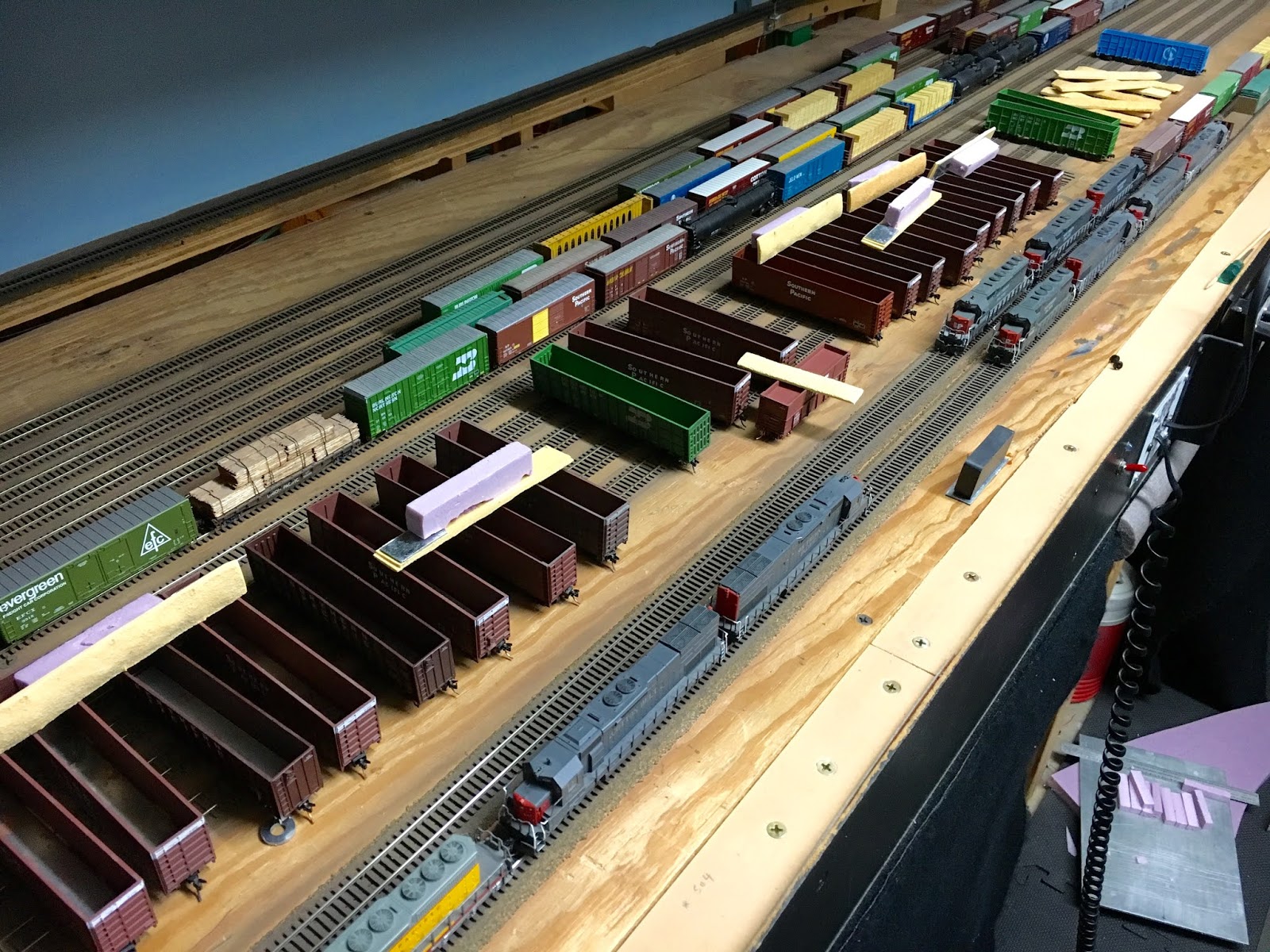
One of the biggest stumbling blocks for the layout having a continuous operating scheme here (ending and restarting ops at any point), had been the large amount of woodchip car loadings. There are currently close to 40 chip cars on the layout moving between the paper mill, staging, and lumber mills.  With all the non standard load sizes the chip cars required, it didnt seem very practical to utilize removable loads. Another issue was how to empty each of these cars without having to lift (or reposition) them from the layout, to avoid excessive handling. I had been restaging each car between sessions manually, which was a big pain anyway. I needed a way to load and unload the woodchips!  After diving into the use of JMRI Ops, I knew I had to figure a way to make the fleet of chip cars have interchangeable loads. The idea of staging identical car numbers and using the program to swap loads and empties sounded ok, but trying to acquire a loaded and empty version of each car number now days is dismal with manufacturers today releasing only one limited run of models (too late now). 
The solution was a magnetic chipload removal system, and a numbering scheme for each car and load that was still semi-interchangeable.  


I glued a steel piece of 16 ga steel to the underside on one end of each chip load. A nominal sized ceramic magnet lifts the load readily as long as the load is not too tight fitting. 


A block of pink foam was glued to the load to expedite loading, so that it would seat evenly and not fall too deep into the cars. 


Since the load length was typical, but the width was not, I still had to number each car in a class to match loads numbered for multiple classes. This allows a variation of 4 different load types to fit multiple cars but mostly +/- one load tolerance size either way. I have a total of 6 load sizes (labeled as ABC, BCD, CDE, DEF), that fit those various car sizes. This system has proven to be fairly user friendly, and pretty reliable so far. 
Cars move from industry via locals to yard, then via manifests to staging, and eventually reverse the process to destination for load exchange. There is always enough overlap between movements to allow the sessions to continue without loading/unloading interaction during ops.
Now we can run up to a full day of ops, and pick up where we left off with minimal interaction as compared to the restaging I had previously been saddled with. 

With the visible car load plan now working smooth, I returned to updating my latest revision of JMRI Ops, which has already been refined multiple times over the last couple years, but is finally working pretty well. I put a printer under the layout to actively print out manifests for easy access to new paperwork. Trying to deal with a full keyboard and monitor around the layout is at times necessary, but not very user friendly, so am also remotely running the Ops program from iphone to the printer with VNC during sessions. This allows manifests / switchlists to be printed for crews and the yardmaster as the trains arrive and depart.  Need to squeeze in a trial run utilizing the CATS program to notify JMRI that trains are arriving, so that the later will build trains automatically, with less me... 

Lots of projects to get caught up on here in print, but if this posts well (already see some issues), I can resume postings again, or at least till technology gets ahead of me again.
:)
Happy RRing