Signaling on the Oregon Division
A couple guys were interested in an earlier signaling thread out here, so I thought I would share what I was up to.
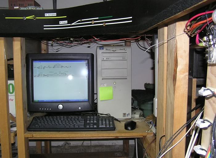
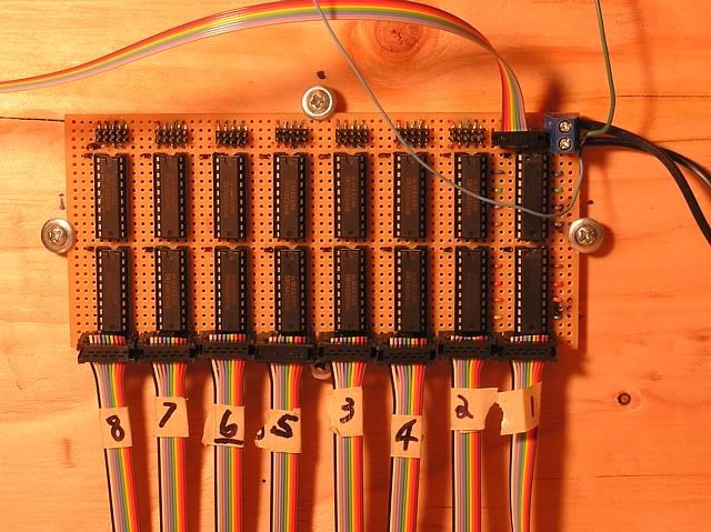
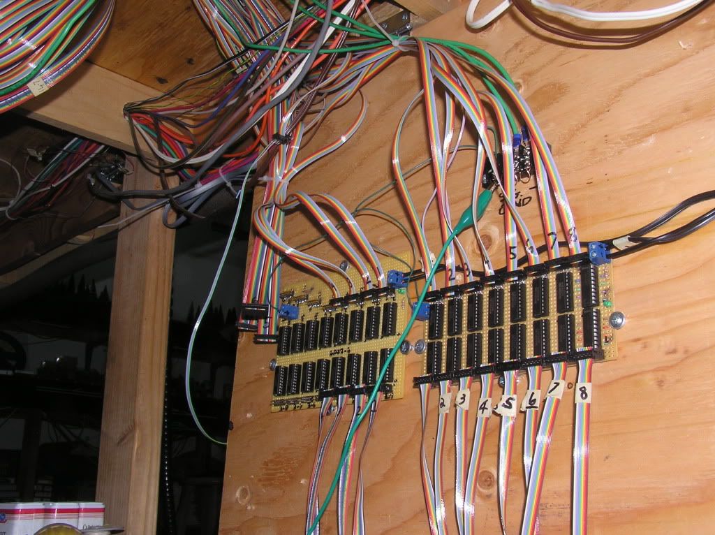
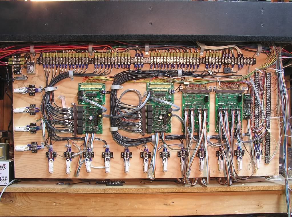
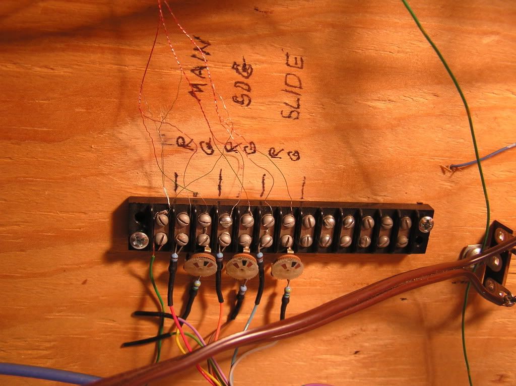
Even though the layout has a long way to go before putting in all the finished signals trackside, we've been working toward getting things ready for an operational system. Some signals are in hard to view locations, and others have not yet been installed, so repeater signals are going to be installed for all locations on the fascias. This will allow operations with the signaling, and as each section on the layout gets more scenery, then the finish signals will be installed. I have been using a magnet board for dispatching, but with my trackplan it has been brutal keeping track of which train is which, so Transponding with occupancy detection was the original goal when starting this project. The intent was just to give the dispatcher a break from that magnet board, but the project quickly turned into a full blown CTC signaling project. Thanks to some help from a couple fellow operators, we just recently completed rewiring for blocking of the different detection sections, along with the incorporation of Transponding. Still have to land the last few wires for the booster section on the terminal strip, and was having some issues with the Transponding, but think I have found a work around now... Now with the layout trackplan viewed on a monitor, each track section lights when a train is in the block, and the train lead engine number shows up under the lighted section. Here is a progress shot of the wiring on the panel board:
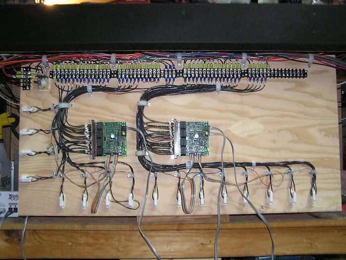
The panel swings up on hinges to make use of the space under the layout for storage. The upper left is power coming in from the Digitrax command station, which goes to the adjacent relay. The relay allows the layout to be isolated from a single track section used for programming. We hooked up a toggle to control the relay that has a blue (men working) LED wired in to designate the layout power is off, and the isolated block is actively in programming mode.
When the toggle gets thrown back, the layout power is routed through to the two Digitrax Block Detection boards (BDL168s) on the left / center.
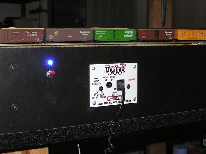
The white coils around the perimeter are the Transponding coils (RX4s) that give the loco ID (I use the lead engine number) to the Block Detection boards. There are a total of 32 separate blocks on the layout each fed with a #12 wire and #22 ga track feeders. The Digitrax Loconet buss transfers the data to a computer under the layout, and to the home network for the dispatcher desk.
Next hardware step is installation of the Digitrax Signal boards. It is going to be a tight squeeze on the panel board, as devices are now going to be added that were not figured in when I built the panel.... The real killer was the required spacing needed for all the Transponding coils.
Software is progressing with a basic layout done for testing with JMRI, and eventual CATS overlay.
Special thanks to Ray Eiser for his R+D in this project.
6 / 2009
Just isn't the same as detailing locos and kitbashing rolling stock (my fav), but here is the latest progress on the CTC signaling project.
Being a signal junkie (thanks to railfanning and my use of ATCS to chase the trains), I am highly motivated to keep moving forward even with the latest hurdles.
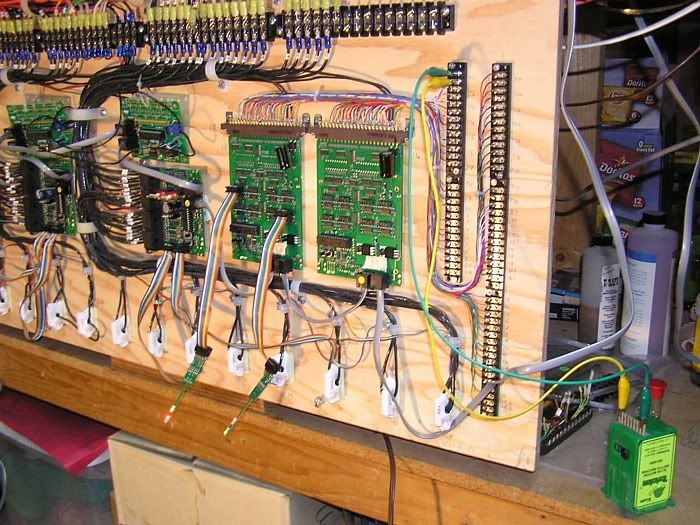
Here is the latest panel shot with the addition of the two Digitrax SE8C signal cards on the right, two almost complete I/O Loco cards built and programmed by Ray (center top), as well as the new terminal blocks where the ribbon cables will fillet off to feed the different components (on right). 16 conductor ribbon will be used to each OS from the panelboard, that will include all wires for signal heads, turnout position sensing, as well as turnout control.

Preliminary testing of a Tortoise motor and signal heads after initial addressing of the new boards.
The signal cards will control the signal color outputs via JMRI commands, as well as driving the CTC Tortoise motors, including the inputs to control normal and reverse on the turnouts. The dispatcher will be able to throw the turnouts from his desk, with the option for operators to throw turnouts from the fascia when not running under dispatcher control.
The I/O Loco cards also interface with the Digitrax Loconet system, and will start out mainly for monitoring switch position. These are some really cool boards, as they can do an array of functions. Some of my Tortoise motors are over 10 years old and have shown the potential to stall before throwing completely. Once they cylcle a number of times they are usually OK, but the I/O cards will be able to verify switch position to the DS making sure that it is actually lined how the dispatcher has intended. These cards will also be used for our switch-locks where yard leads enter the CTC sections. This will provide protection from crews lining their trains out onto the main without DS authorization. Another feature these cards will provide are the future working dragging equipment detectors and simulated hot box detectors that will be trackside. Anyone have any good shots of the circa 70's draggers with red beacons, and hot box detectors (I'm on the hunt for more)?
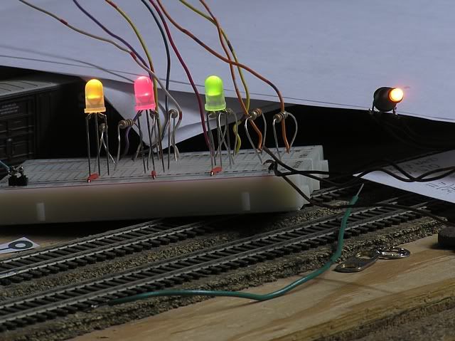
We have done extensive LED testing to get proper color and brightness for the fascia repeater LEDs and Sunrise target signals so that they look accurate. After getting that to where we were content, we hit a block wall yesterday while testing the outputs from the signal cards for LED brightness.
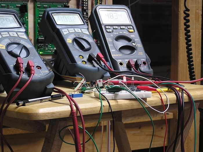
As you can see in this view, the brightness of the LED is more than quite limp.... and this is with the LED straight off the signal card with no resistors used at all!
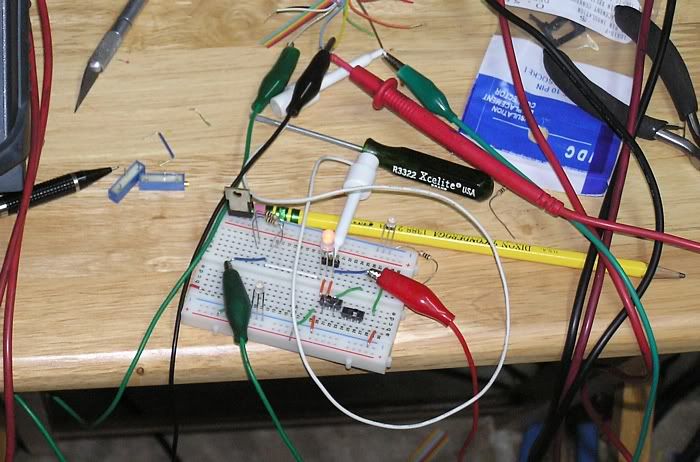
The Digitrax SE8C cards appear to only put out 4ma which is nowhere near enough to match the needed current for any of our signals, so now we have to build a circuit to boost outputs to the signal heads and fascia repeaters. This will slow us down, but are currently looking at use of optoisolators vs. buffers to give us the needed increased output.... Sorry if too tech, hope some of you other signal enthusiasts can make use of the info.... especially if using the SE8C cards.
7 / 2009
Finally scrounged up a pic of a scanner / dragger from somewhere along the Espee. A poorly scanned image from the unknown... The three white lights informed crews of which side the hot box was on (or if there was more than one hot box), and the large numbers illuminated the axle count on the location in the train. Sensors were on each side of the railhead monitoring bearing temperature. The beacon was a red rotating light triggered by a rubber flap that pivoted when equipment drug over it.
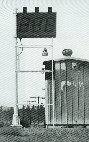
We have a plan for a working dragger to catch trip pins and the likes. The scanner will have to be a random event from one ops session to the next. Part of the new I/O boards will be monitoring / controlling the events from these.
Any more pics more than welcome.
Coming soon to a layout near you. :)
8 / 2009
The cure for the SE8c current outputs being too low, was designing and building a couple buffer boards to boost the amperage needed to get the LEDs up to the proper brightness. Thanks to Scott Schifer for his engineering expertise, he was able to analyze the Digitrax card and compile a drawing for us to work from. Ray is building the two buffer boards (one for each SC8c), and we have the first buffer up and running in test mode now. I'm guessing roughly 300 solder connections per board!
Incoming signal aspects are fed on the bottom with the ribbon cables from the SE8c. The signal outputs on the top will head out to the field, with the remainder of the 14 ribbon strands on each multiconductor being picked up from the terminal block section that also go out to the Tortoise motors (momentary switch, motor drive, and position sensing).
The buffer project allowed us to fine tune the brightness and color of the LEDs on the plugboard. The yellow indication was the critical color, because you have to mix just the right amount of green with the red simultaneously to yield the proper shade of amber. This was achieved by varying the resistance values of the two colors in the bi-color LED.
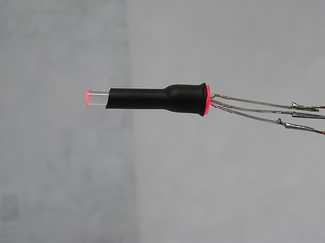
A sample of the light tubes that will protrude through the fascia at the appropriate signal locations was made simply by taking heat shrink tubing and putting it over both the LED and clear tubing together. The light tube helps to remove the directional viewing of the yellow indication, and with a light coating of pearl white over the end, the blend is excellent. Side view with the red aspect:
These locations will have diagramatic signals with masts, which will include number and grade plates as needed.
Content on brightness and how the colors are on the LEDs now, we moved on to installing the first set of controls and sensors for the Tortoise at East Oakridge. When Ray finishes the other buffer card and we get the artwork for the fascia signals settled, we should be in Run 8 moving from one OS to the next. Networking on the PC has now evolved to where I have to keep an eye on Ray so he doesn't start operating my locos over the internet from his house, as the intent is to work through further JMRI programming. Slow progress, but making steady headway.
11 / 2009
Too much overtime kept work at a slow rate for a number of months. Recently made some great progress towards running the layout under CTC control. Picking up from where I last left off;
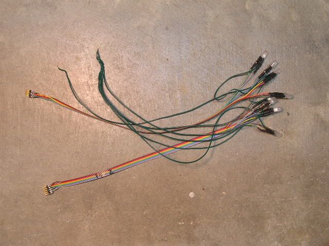
Made mini ribbons with the LEDs and resistors prefabbed on the ends to feed the repeater signals. Ray was able to bang these out at his place, and we just plugged them into the IDC connectors when I got time to mess with the layout.
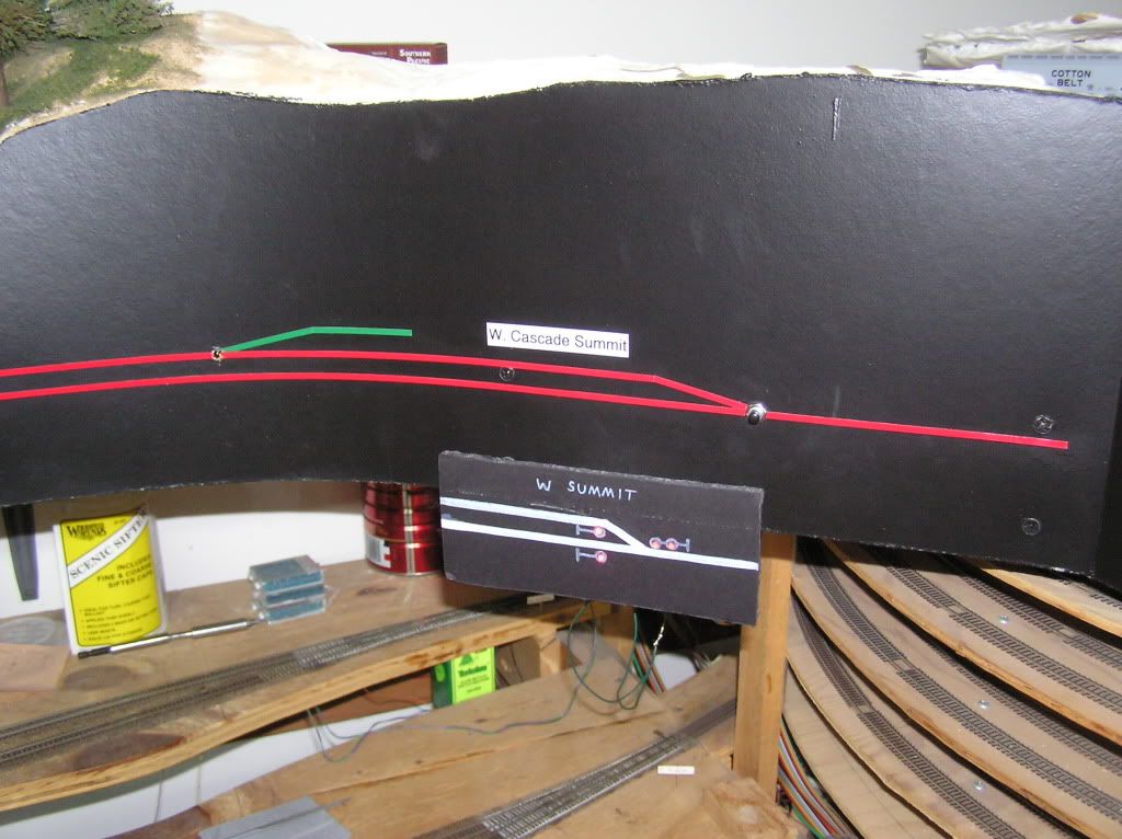
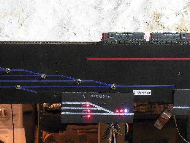
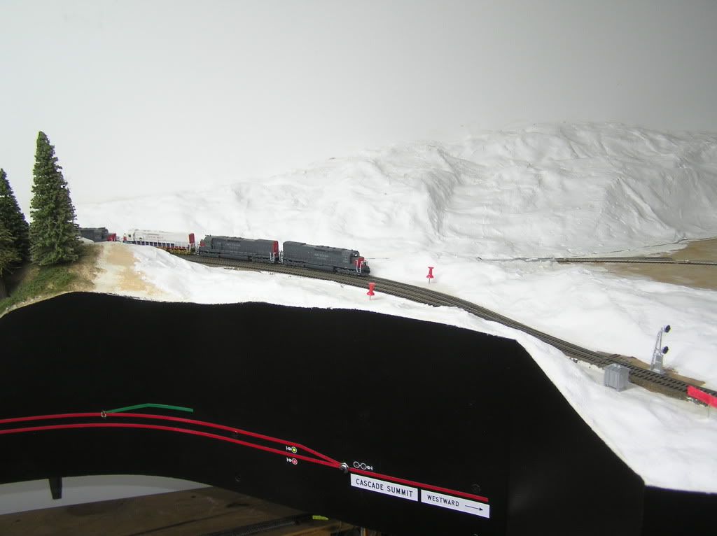
Here is a shot of one of the typical but temporary OS locations, for use until our artwork is completed for the fascias:
Then come the installation and construction / kitbash of more layout signals. Sitting on a load of BLMA signal head kits where there are exceptions to the Sunrise target signals on the layout... ie some Cantalivers and tri-head lights. Just around the corner, the layout signals will begin to get installed to all the terminal blocks that have been set under each OS location, fed from the same ribbon theat feeds each OS repeater. Unfortunately they will have to get R&Rd as each section of scenery is put in...
1 / 2010
Continuing progress on the buffer cards. SE8C feeds come in the bottom, and boosted signal outputs go out the top to the field locations on the layout.
Finally had our first beta test / ops session last week. Remote dispatching worked out well using Teamspeak2 with a few FRS radios. Good times with a CTC controlled layout. Just something about staring at an OS with all reds, and the anticipation of the DS lining the turnout for your train, followed by his signal indication coming up for you to proceed... Ray has a pretty good grip on the "Approach Lit" display for all the signals now.
We have set up the first "Lunar / Red" aspect signal indication at the East end of Oakridge, for traffic entering the yard lead.
Beta JMRI panel screenshot on the layout computer. This layout is used for ABS when there is no dispatcher to take the heat.. lol (no one to run CTC that is)...
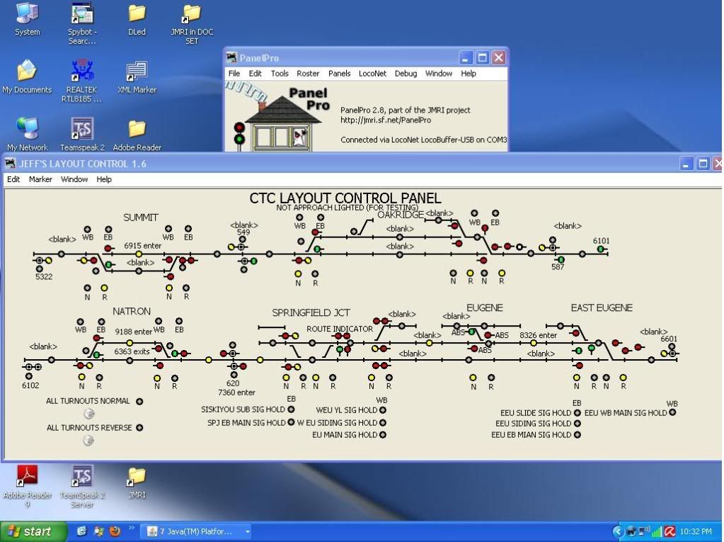
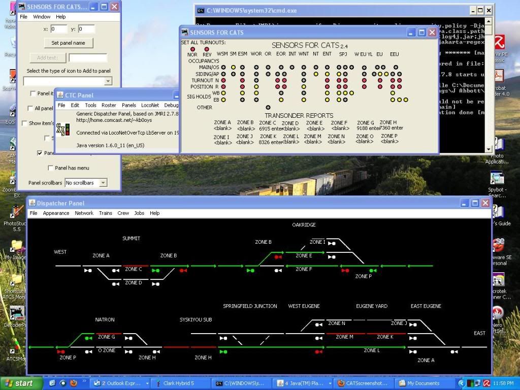
Beta CATS panel screenshot from the dispatcher's desk. This layout might appear to be incomplete when comparing with the JMRI panel, but it only reflects the actual CTC sections of the layout the dispatcher needs to use. The JMRI panel is basically the automatic controls that takes place out in the field at each plant, and the CATS is the overlay that the dispatcher controls directly to sensors on the JMRI panel. There are sections that stay ABS inside yard limits also (the Yard Master controlled areas).
2 / 2010
Have to add more resistive wheels to keep the occupancy up while trains pass through each OS. Here is the first caboose to get it's wheels set up for block detection with surface mount resistors:
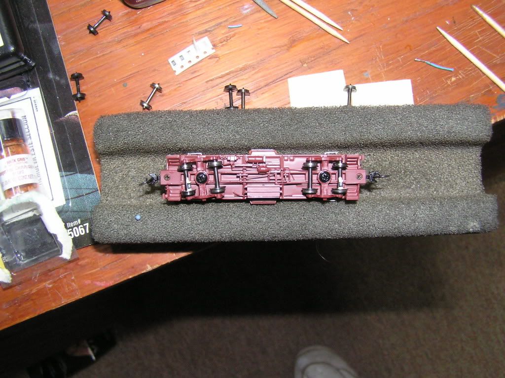
Special thanks again to Ray for his expertise in this project!
More to come!
3 / 2010
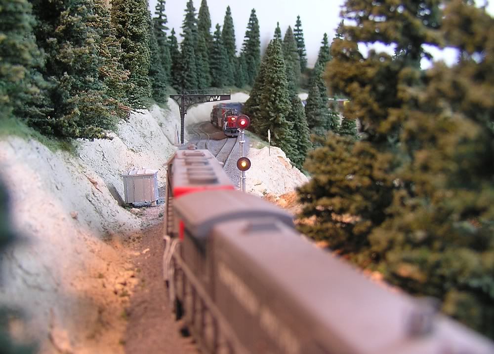
Been running lots of loose ops sessions to make sure we have all the bugs worked out of the programming. Dispatching CTC over the internet is working out really well. Decided it was time to put a little icing on the cake, so pulled out some old Sunrise signals that have been sitting in boxes for a long time and began the install of the finish layout signals. Here is a shot of a red over yellow as this westbound gets a diverging into the hole for a non clearing eastbound that is holding the main. Good times on the Espee Oregon Division.
9 / 2010
OK, so it's been a couple days since I posted any progress.
The latest image of the layout control panel. BDL168's, SE8c's, BD4, Loco IO's, and Transponding Coils, all control the layout... The pony tail on right is the spare field wires. The backside supports the buffer cards (SE8c amplifiers), and power district protection (PM42s).
Signals are going in at a slow pace, but at least I figured a way to protect the signals as I move forward with plaster and other scenery.
I have now installed all of the permanent signal repeaters in the fascias. The artwork highlights signal placement where the LEDs are, courtesy Ray Eiser and David Curlee. They also provided the labels for the station names etc, ...with the correct Egyptian font as used on the old Espee. Thanks guys!
Another view of the fascias below... here, the upper deck is the "before" with the temporary foam board holding the repeater signals, and lower is the "after" with them installed in the fascia.

10 / 2010
Here is how the signals are connected to the ribbon cables (via terminal block). In line resistors protect the signals, and the trimmer pots are used to fine tune the yellow indication to it's proper color. Those tiny signal wires are a bear to work with!
11 / 2010
So here is the real meat and potatoes for me. Note the absolute plates on the sigs, along with the center target that got it's background trimmed for the close clearance of adjacent trackage as per prototype. This just screams Espee! Signals are approach lit, so no indication until there is an occupancy on their track. Aint' those Sunrise signals beautiful? Most of the sigs installed as of late are along the plywood prairie, so I'll spare you for the most part.... so much for getting the scenery in before the signals. lol

Put some temporary signals trackside until we see some of Craig's signals hit the market... I am about out of Sunrise sigs now, but I might have to kitbash some more if my patience gets any thinner. Here Ray whipped up some tri-color SMD LEDs to act as pot signals... sweeet! The thumb tacks represent signal locations and stay to protect the temp sigs for now.
03 / 2014
Now that the expansion project is behind us, and all fascia repeaters are working, starting to push forward on the layout signal project.
Originally I started out using the Sunrise signals to control the layout trackside, but they stopped production before I acquired enough, and Dan never offered just a working head to put on cantilevers and bridges. Not satisfied with the current offerings of H2 target signal heads that were available when we started this, we have taken to modifying the early static Sunrise design for use on the layout. These are scarce to find now, so a friend cast all the parts from the Sunrise originals (thanks Paul!), so now we have a sufficient quantity to follow through on the project.

Ray developed a way to utilize 0603 bi-color LEDs that have correct RR green and red colors, with a real close yellow mix... With the small size of these LEDs, they fit inside the casting of the scale H2 head without having to sacrifice the back of the head or any of its other details. The leads come out the bottom and simulate the flex conduit, with a bottom cap to seal the drilled out section. This is a view looking at the bottom of the head.

By drilling the lens opening in the signal head casting to proper size, we insert a scale clear lens tube that is used as a diffuser. By placing the LED behind the lens, the light is dispursed very well. This shows one of the LEDs with the leads attached, next to one of the cut lenses.

Here is a progress shot of one of the heads we have been testing with:

Most of the heads will be used on cantilevers and bridges, but a number are also needed for pot signals. For those that need the rest of the signal assembly, it is pretty straight forward kitbash as has been achieved here before on a previous project. On that signal bash project I tore down a couple 15' high late version Sunrise signals to rebuild them as the taller 20' versions. Even with the oversize light housing (head) that contains the LED, these are nice signals all things considered. Basically the only reusable parts were the relay boxes and heads, so had to install taller masts, new ladders, number plates, etc. I was able to come up with pretty clean modified versions that have been in service on the layout for years now. Here is a shot of the bashed signals before painting:

The methods will be duplicated in our signal build project now, but will use our castings, and our LEDs installed in the original more scale size heads. Now that we have completed testing and fitting, along with acquiring all the needed parts and materials to build these, we are ready to do a production type assembly procedure. Ray has completed a first run of 16 LEDs with the attached leads (as pictured above) to get the first assembly run started (thanks Ray!)
First installs I am figuring will be used for pot signals, then move forward to installs on the NJ cantilever kits that have been sitting in boxes for long enough. We are in hopes of completing enough heads in a limited number of build sessions to fill in the missing pieces without too much grief ...
04 / 2014
The layout's expansion project resulted in a new set of panels to control the CTC signaling system.
The long term plan is to build an actual working CTC machine to fit the era modeled, but the ATCS model via computer, is a nice stand in for now.
These two screenshots were taken at the same time, which shows how the signaling is reflected between the two programs.
Here is the latest revision of the CATS dispatcher panel that handles the Control Logic:

...the latest companion JMRI Signal Control Panel:

04 / 2016
Will post pics of the new Century Foundry H2 signal progress once I get to building that inventory here... Meanwhile been constructing the custom design reported above. Thanks goes to both, Paul for providing the castings, and Ray for his help in R&D. The first few efforts were enough to make me abort the project (think 10 lbs of shit in a 5 lb bag), but have finally found some methods to complete the first few working versions
LEDs installed in first few heads:

A couple with the arms, and one with the start of bracket for cantilever mount (more on that later):

Lens installed:

First attempt....
This dwarf still needs some light blockage on underside:


Additional backlog for the paint shop includes a number of the old Sunrise versions (also compatible with existing layout wiring):

More updates to come as worthy...