My biggest stumbling block for this project was replicating the extended draft look as used on Espee's Hydra-Cushion fleet, so Don (another one of my crew members) machined me up a fixture to make adapter plates to mount the couplers to, which in turn mount to the car's underframe. The holes in the new adapter plate line up with the existing hole on a MT underframe (using 00-90 screws), but have to be drilled anyway for other cars. I use a Square mounted to the drill press to align underframes, and mass drill the new hole location on similar cars one after another. My new adapter plates are designed to work with the 1023 coupler box for a reasonable finish look, but for now I am banging out the project to get up and running by using the coupler cut from the Talgos. Fortunately these have the same hole dimensions and I can upgrade quickly by just swapping the coupler boxes out later.
Here's a few pics of what I have going for now:
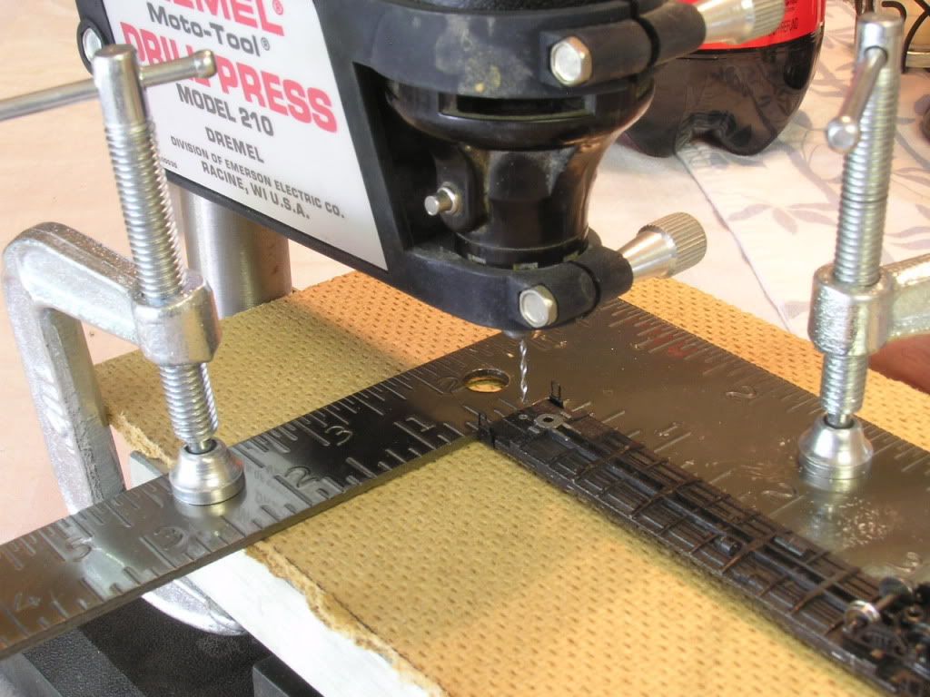
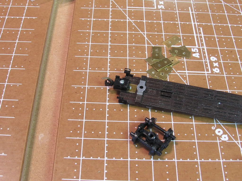
This is the set-up used for drilling the underframes. Simple, but once I get the layout set for the first car, I can just keep drilling the holes on all the underframes that require the same dimensions.
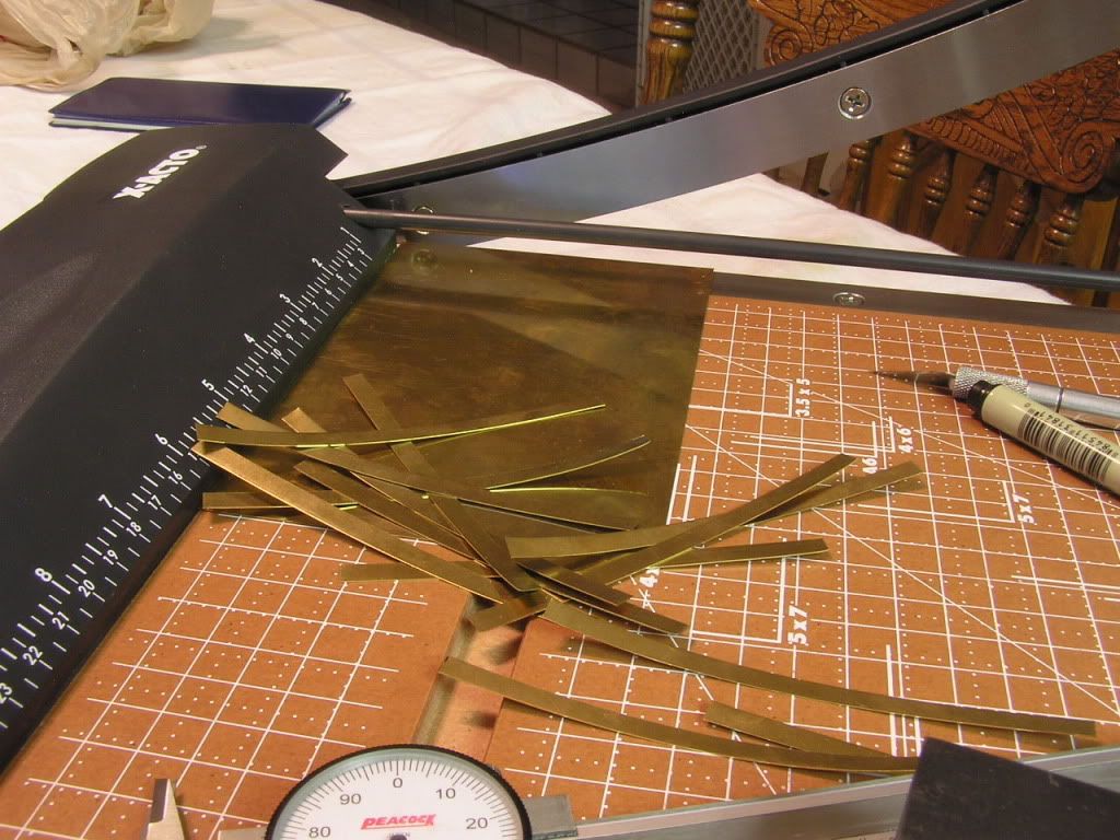
I cut strips of .010" brass on a paper cutter to the desired width and length
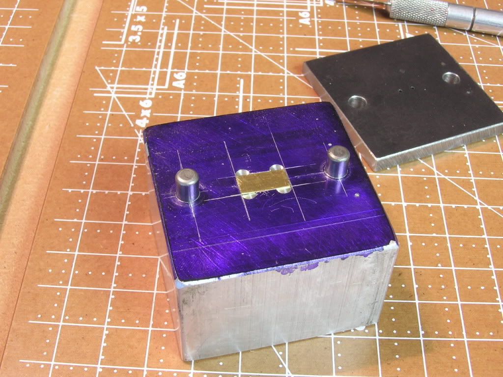
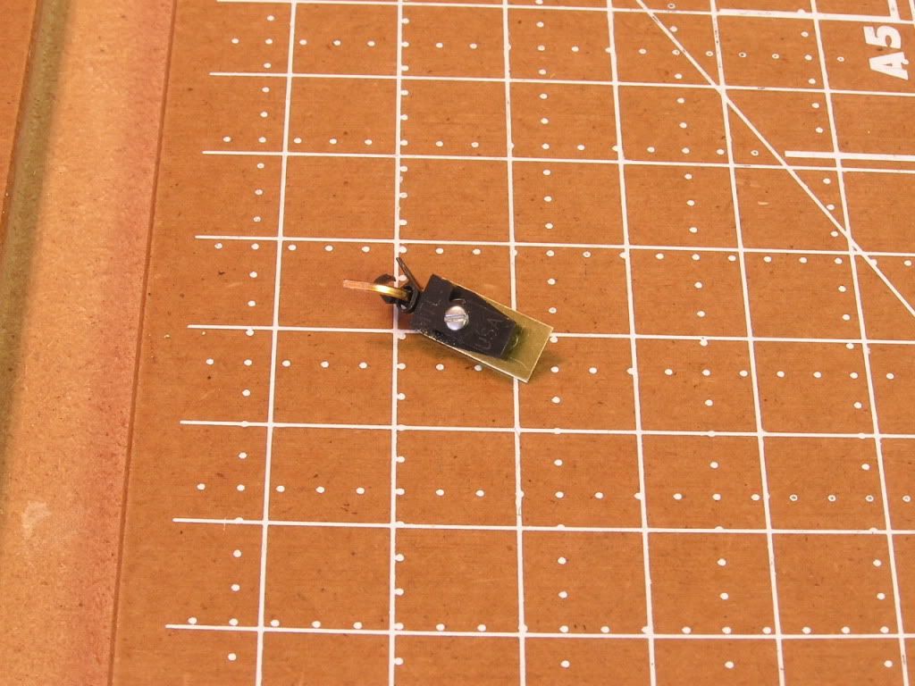
The fixture has a slot to hold the brass adapter piece, and the cover has two holes in it that are kept in alignment via the fixture's line-up pins. With the cover on the fixture it only takes seconds to get the holes drilled with the proper spacing and alignment that was previously killing me in my atttempts doing one adapter at a time.
The underframe gets shaved down so that the car height is closer to what it should be which also is how I match coupler heights. The screws need to be cut flush with the adapter piece on both sides if using the 1023 box. Then I notch the ends of the car body so the coupler fits up snug underneath. I just cut off the talgo coupler with a dremel wheel and file.

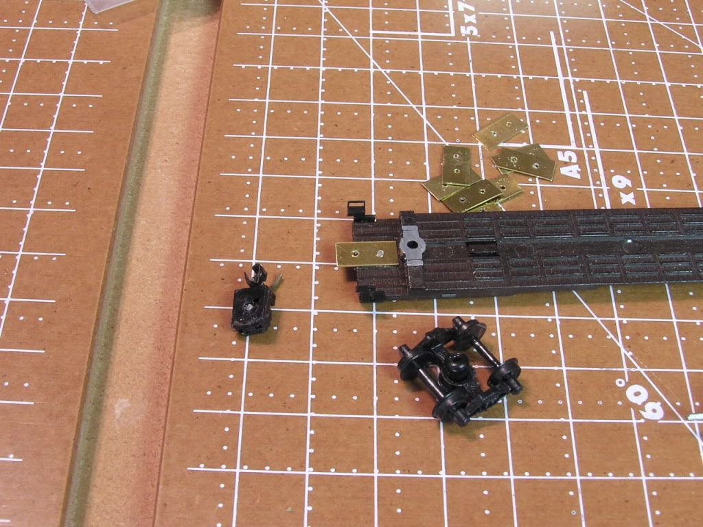
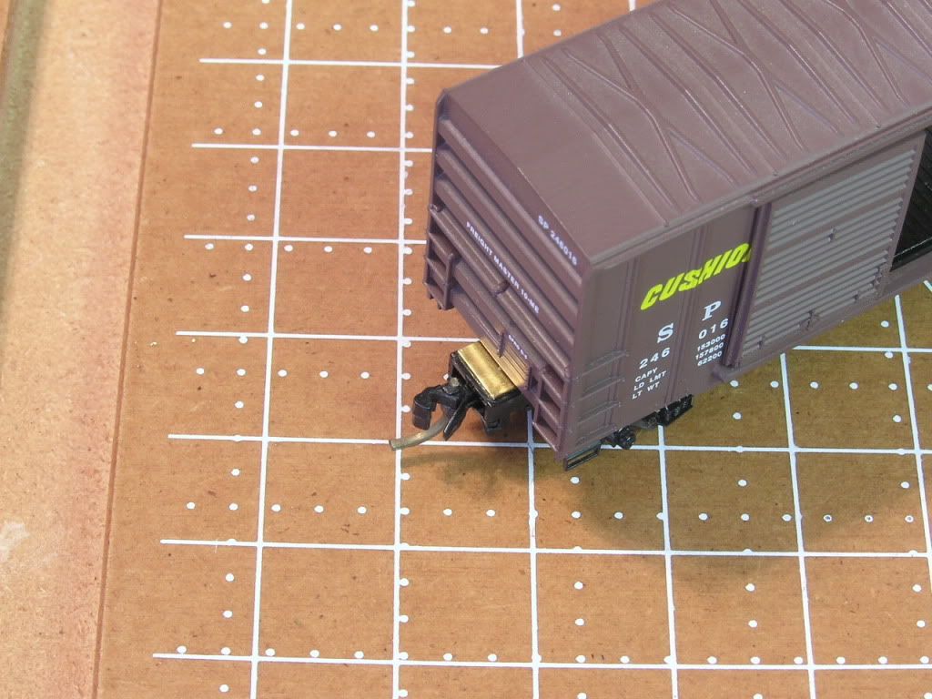
A shot of the 1023 sample.
The coupler box extends out to the same distance as on the talgo extended bolster truck.... just needs some matching paint.
Still takes some time, but mass production like this has really helped speed up the process and keep me motivated. Operations are a real kick with a helper crew in the mix!
Hopefully some ideas here you guys can use if you are headed the same direction.
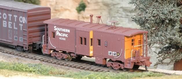
Well, thanks for the comments guys, but this ain't the first time I tried body mounting. For museum models like on this hack that has extended draft, I have used 1023's filed thinner and painted to match:
I had a small number of body mounts done on freight cars over the years, but never enough to run full trains of them as is part of the agenda now.
And as far as writing any more articles, LOL... at least there is no middle man to bungle that up with a blog.
I always wanted someone to etch them, but that just might be one of my next projects on the horizon!